All our technology contains electric circuits, from household appliances - such as a kettle - to advanced medical equipment. It is an important topic in GCSE Physics and you are expected to understand the fundamentals of electricity and its applications in the world around us.
This guide will cover the key concepts behind electric circuits, including the series and parallel circuit types, key features like resistance and practical experiments to reinforce your knowledge. It is suitable for GCSE revision of all major exam boards, including AQA. If you need more support with this topic, TeachTutti has a list of GCSE Physics tutors who can help you revise electrical circuits online or in person.
Understanding electric circuits
What is an electric circuit?
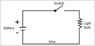
An electric circuit is a closed loop in which electrical energy flows. It transfers this energy to devices or components, giving them power.
A circuit needs three elements:
- Power source: This provides the energy that drives the flow of electric current e.g. a battery or mains electricity.
- Conductive path: This is normally wires made of conductive materials, like copper or aluminium. It lets electrical charge to flow freely.
- Load/component: Devices or elements in the circuit that use the energy e.g. a light bulb or motor.
The loop needs to be complete and closed for the current to flow. If the circuit has a switch in the "off" position, this stops the flow of energy. A closed circuit like this is needed for lights or phones to work.

Key electricity components
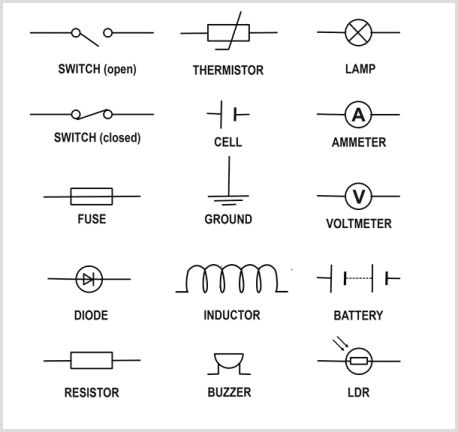
The symbols that represent components in a circuit are standardised. This makes it easier to see and design electrical circuits.
These are the most common symbols:
- Battery: The source of electrical energy. Multiple cells are needed to create a battery.
- Resistor: This is a component that reduces the flow of current. This could be to protect other components or control current levels.
- Lamp: Turns energy into light and heat.
- Diode: Lets the current flow in a particular direction. It's often used in electronic devices.
- Switch: This opens or closes a circuit, controlling the flow of electricity.

1
What do you need for an electric circuit to work?
Types of circuits
Series circuits
All the components in a series circuit are joined in a single, continuous loop. There are specific properties of this type of circuit:
- Current: The current in series circuits remains the same. The amount of charge is the same that passes through each component because there is one path for the flow of current.
- Voltage: The components share the total voltage from the power source. For example, if there are 3 bulbs and a battery with 12V, each bulb will receive 4V.
- Resistance: The total resistance in a series circuit is equal to the sum of the individual resistances. This is written as Rtotal = R1 + R2 + R3. The resistance increases if more resistors are added, reducing the total current.
A negative feature of a series circuit is that if a single component fails, the entire circuit is broken and the current flow stops entirely. An example is older Christmas lights: one faulty bulb would turn off the entire string!
Parallel circuits
Multiple branches or loops connect components in a parallel circuit. There are advantages to this configuration:
- Current: The total current is divided among the branches of the circuit. The amount of current in each branch depends on its resistance. The total current flowing out of the power source is equal to the total of the currents in each branch: Itotal = I1 + I2 + I3
- Voltage: The circuit branches receive the full voltage from the power source. If a 6V battery is used for two bulbs in parallel, the branch will send the full power to both branches, giving each bulb 6V.
- Resistance: The resistance of the circuit decreases when more branches are added. This is due to more paths being added for the current to flow through: 1 / Rtotal = 1 / R1 + 1 / R2 + 1 / R3
Modern home lighting circuits use parallel circuits because a single branch can fail without affecting the other components. In other words, one bulb can go out and the others will remain lit.
Mixed circuits
Some circuits use both series and parallel components. A string of lights may use parallel branches to keep most bulbs working if a single light fails, while each branch contains a series circuit. The analysis of these circuits needs to be carefully done, following the rules for both series and parallel circuits.
2
Which statement is correct about parallel circuits?
Core concepts
Electric current and charge
Electric current is the flow of electric charge that is carried by electrons. The formula for the amount of charge flowing past a point in a given time is Q = I × t:
- Q = Charge in coulombs (C)
- I = Current in amperes (A)
- t = Time in seconds (s)
For example, if a 2A current flows for 5 seconds, the electric charge is 10 C (Q = 2 × 5).
An ammeter can measure the current. This is connected in series in a circuit.
Potential difference (voltage)
Voltage is the energy transferred through a component per unit charge. It is also known as the "push" that pushes the current around the circuit. Voltage is measured in volts (V) and calculated using Ohm’s Law, V = I × R:
- V = Voltage in volts
- I = Current in amperes
- R = Resistance in ohms
For example, the voltage is 20 V when a current of 2A flows through a resistor with a resistance of 10 ohms (V = 2 × 10).
Resistance
Resistance is how much a component opposes the flow of electric current. Several factors affect a component's resistance, including its material, length and cross-sectional area e.g. copper has low resistance, while a rubber insulator has high resistance.
The total resistance in a circuit depends on whether the circuit is in series or parallel, which affects the current and voltage. Resistance is calculated using Ohm’s Law, R = V / I.
Power in Electric Circuits
Electric power is the rate that energy is transferred in a circuit. It is calculated using P = V × I, where P is the power in watts (W).
The following formula can also be used, which combines power with resistance: P = I2 × R. This shows that power dissipation increases with higher current and resistance.
3
What happens to resistance when branches are added to a parallel circuit?
Practical investigations
Investigating resistance
Resistance is an important consideration in the functionality of electric circuits. During your GCSE Physics, you will conduct experiments using wires of different lengths and materials.
Key variables:
- Length of the wire - Resistance increases with length. The electrons have to pass through more material in a longer wire, which leads to more collisions and greater resistance.
- Cross-sectional area - There is less resistance in thicker wires as they have more space for the electrons to flow through. This leads to fewer collisions.
- Material - Different materials have different levels of conductivity. Copper and silver are metals with low resistance. The alloy Nichrome has a much higher resistance.
- Temperature - Resistance rises with the temperature. This is because the particles in the wire vibrate more, making it harder for the electrons to flow.
Example experiment
Students may be expected to create a simple circuit that uses a power supply and contains an ammeter, voltmeter and variable resistor. They can find the effect of wire length of resistance through these steps:
- Connect wires with different lengths to the circuit.
- Measure the current (I) and potential difference (V) for each wire.
- Find the resistance using R = V / I.
- Calculate the wire length against resistance to see the relationship.
- Difference between series and parallel circuits.
It is important to test how series and parallel circuits perform relative to each other. The following experiments will show students that series circuits are less efficient due to higher resistance, while parallel circuits are effective at maintaining consistent voltage across components.
Series circuit:
- Use a power source and connect resistors in series. Measure the total resistance using Rtotal = R1 + R2 + R3
- Check how the resistance affects the overall current when you add more resistors.
- Use a voltmeter to test how the potential difference is shared among components.
Parallel circuit:
- Connect the same number of resistors in parallel. Measure the total resistance using 1 / Rtotal = 1 / R1 + 1 / R2 + 1 / R3.
- Measure how the number of resistors affects the current flow.
- What is the potential difference across each resistor? It should be the same as the supply voltage.
Current-voltage graphs
Students will often have to investigate how current and voltage behave for different components e.g. resistors, filament lamps and diodes:
- Create a circuit with a power supply, a variable resistor, an ammeter and a voltmeter.
- Change the current through the component by adapting the variable resistor.
- Record the current (I) and voltage (V) for each setting.
- Plot the values on a graph so you can visually see the relationship.
You should see the following:
- Resistor - the graph is a straight line. This shows a proportional relationship (Ohm’s Law).
- Filament lamp - the graph curves as the filament heats up and the resistance increases.
- Diode - the current flows significantly in one direction, showing its rectifying property.
4
What doesn't affect the resistance of a wire?
Tips for revision notes and exam
Electric circuits are a common topic in the GCSE Physics syllabus. You will often be asked questions on circuit diagrams, including symbols:
1. Formulas
- Memorise key formulas: V = I × R, Q = I × t and P = V × I. Try to rearrange these equations so you can solve different variables.
- Make sure you understand the units. Voltage is measured in volts (V), current in amperes (A) and resistance in ohms.
2. Circuit diagrams
- Recognise and be able to draw circuit symbols for all major components, including resistors, diodes and switches.
- Test your knowledge on complex circuits that use both series and parallel components.
3. Calculation questions
- Make sure you use the correct formula. Show your workings in your answer and always use the correct units.
- Double-check your significant figures or decimal places.
4. Practical application questions
- Can you explain the results of experiments e.g. investigating resistance or current-voltage relationships?
- Use scientific terminology, including "increases", "decreases" and "remains constant to describe change.
5. Common pitfalls
- Don't confuse series and parallel rules. Current is constant in series, while voltage is constant in parallel.
- Don't forget that resistance decreases when you add resistors in parallel. Conversely, it increases resistance when you add them in series.
Final thoughts
Electric circuits show the practical applications of topics covered in GCSE Physics. Experiments and investigations will help you learn how electricity flows, the difference between series and parallel circuits and the impact of resistance on current.
For further reading, SaveMyExams has done an example investigation into potential difference, current and resistance. ExamPapersPractice has practice questions on series and parallel circuits to test your knowledge.
If you need further help, you're welcome to book experienced GCSE Physics tutors at TeachTutti. All tutors have an enhanced DBS check, and most provide a free consultation to meet you and answer questions about their approach to tuition.
This post was updated on 09 Jul, 2025.

